De AN/GRC-9 in gebruik tijdens een velddag
ECDY-88: a rare power supply for the AN/GRC-9
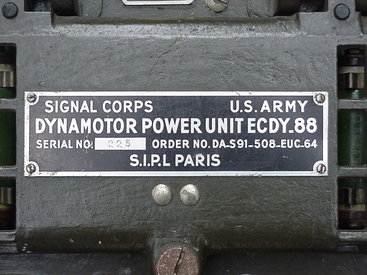
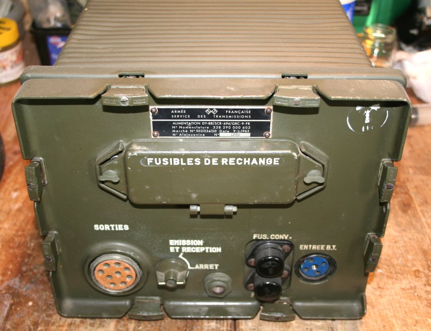
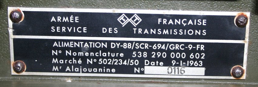
Over twenty years ago Mr. Gerard Deibel found a power supply for the AN/GRC-9 radio at an Army surplus depot in Greece. The ID-tag
tells us that we are dealing with the ECDY-88 made by S.I.P.L. in Paris, France. Note that the nomenclature shows resemblance to
the very well know DY-88 power supply unit. Never I have seen nor heard of this PSU before. Also I was not able to find a trace of
it on the internet nor in any publication. A truly rare PSU indeed.
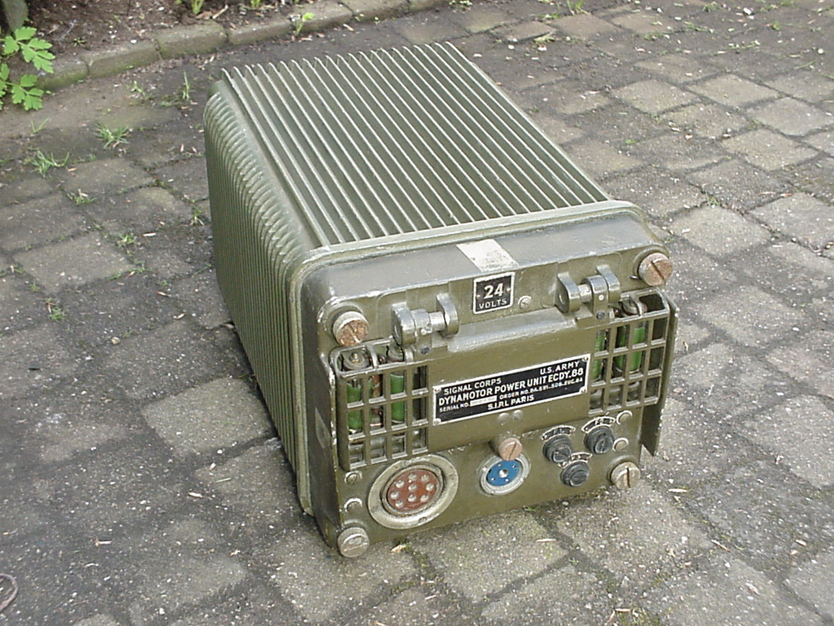
Apparently the ECDY-88 was special designed to withstand heavy mechanical conditions. Probably special for use in armoured vehicles
or tanks. Weight and the free choice of switchable operating voltages were less important since all military vehicles are standardized
to 24 Volts nowadays. The ECDY-88 operates on 24 Volt batteries systems only and weights about 20 Kg, which is 5 Kg more than the standard
DY-88, that weights about 15 Kg.
The dimensions are 40cm deep, 25,5cm width and 22cm high. The two studs for bolting the PSU firm to the vehicle bring in an extra 2 cm
and thus making the actual operational height to 24cm in total.
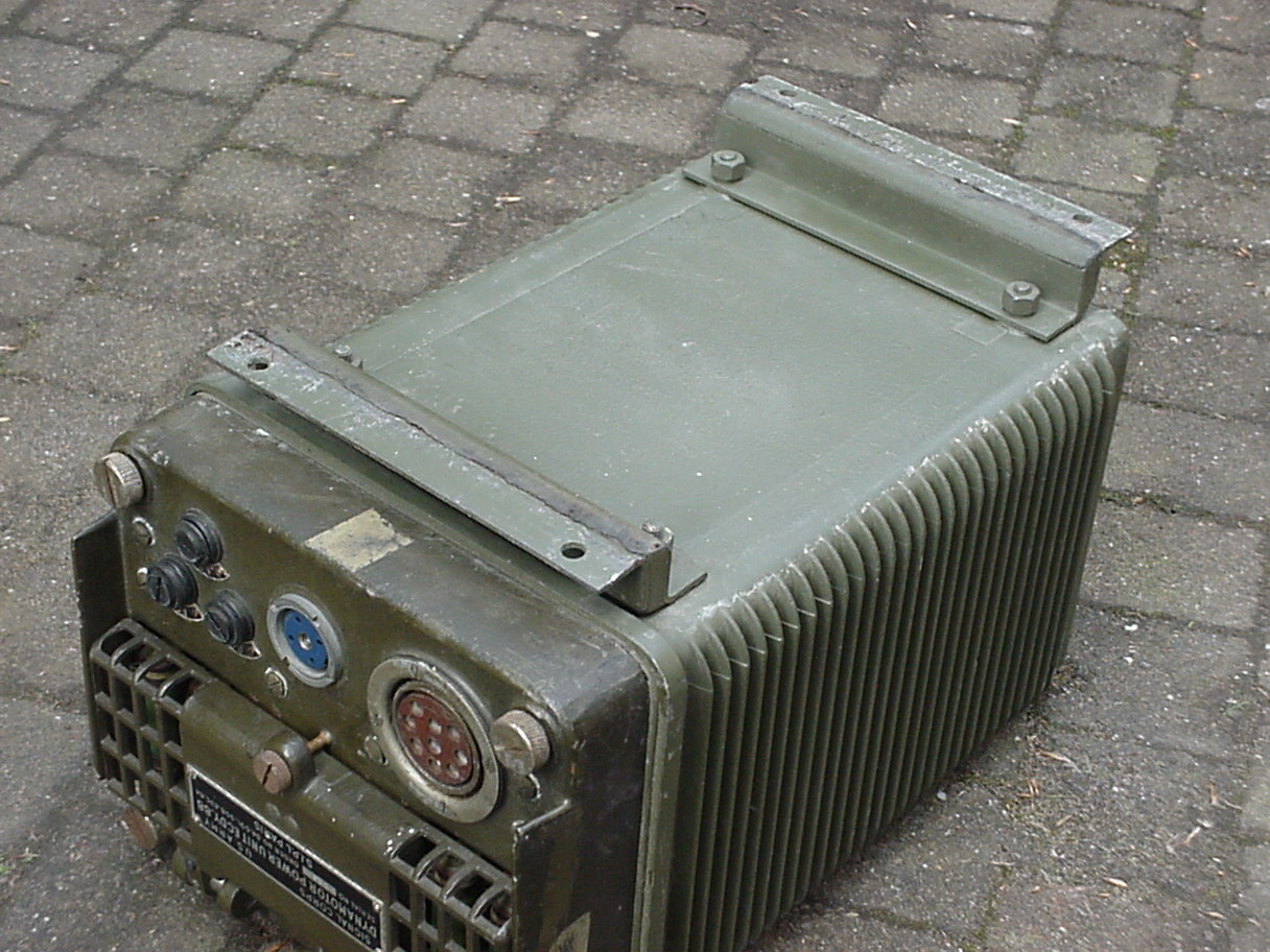
The standard DY-88 can sometimes be difficult to remove out it's case under operational conditions. Depending on how the PSU is actual
mounted in a vehicle it can be hard sometimes to unlock the lower two of the clips that hold the PSU in it's case. The ECDY-88 PSU is
easier to remove out of it's case. The four big screws at the corners of the front are easily reachable and loosen them is the only
handling needed to separate the PSU from it's case.
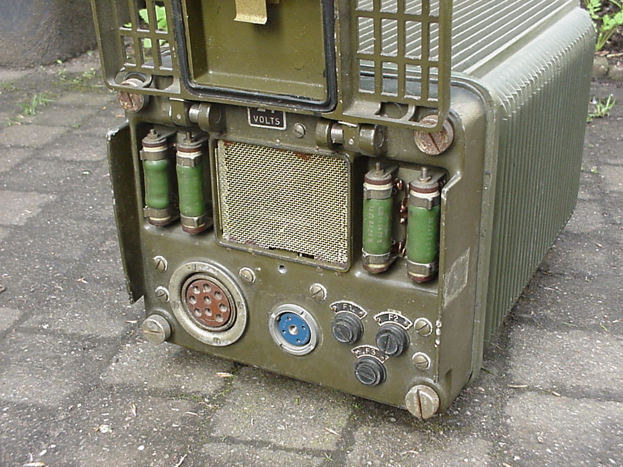
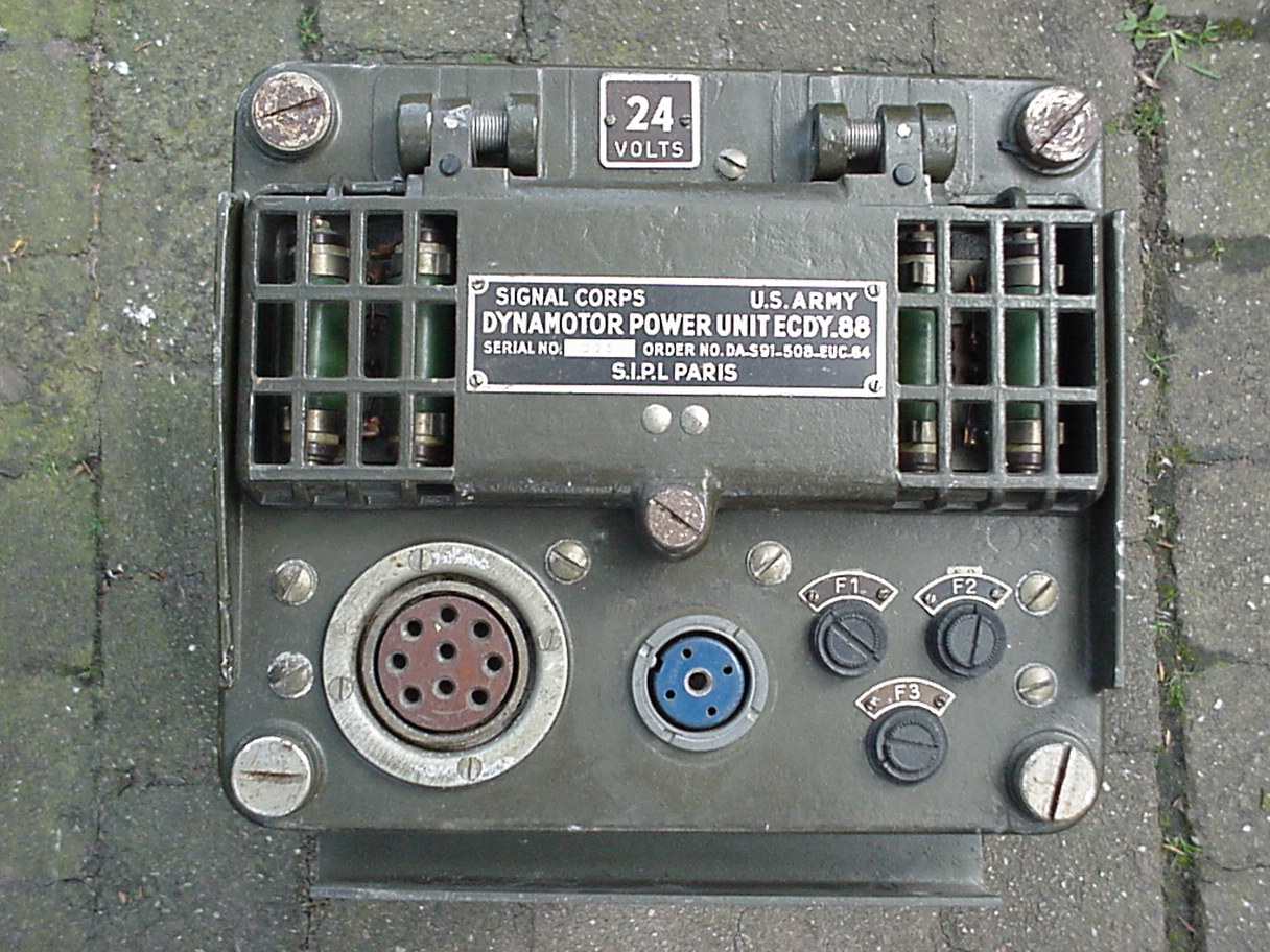
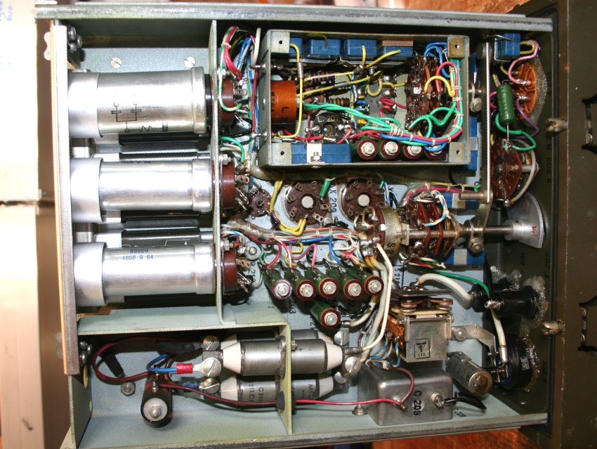
For optimal heat exchange of the dissipated power in the 'large resistors' they are mounted more or less outside the water - and air -
closed cabinet of the PSU. These four resistors can be seen behind the grid on the font that can also easily be opened by just unlocking
one screw. No good design thinking from the point of view of preventing unwanted short circuits. Since the holes in the grid are quite
large someone can easily - by accident - push a metal rod or other object through them, causing short-circuit that may result in damage
of the PSU beyond field repair.
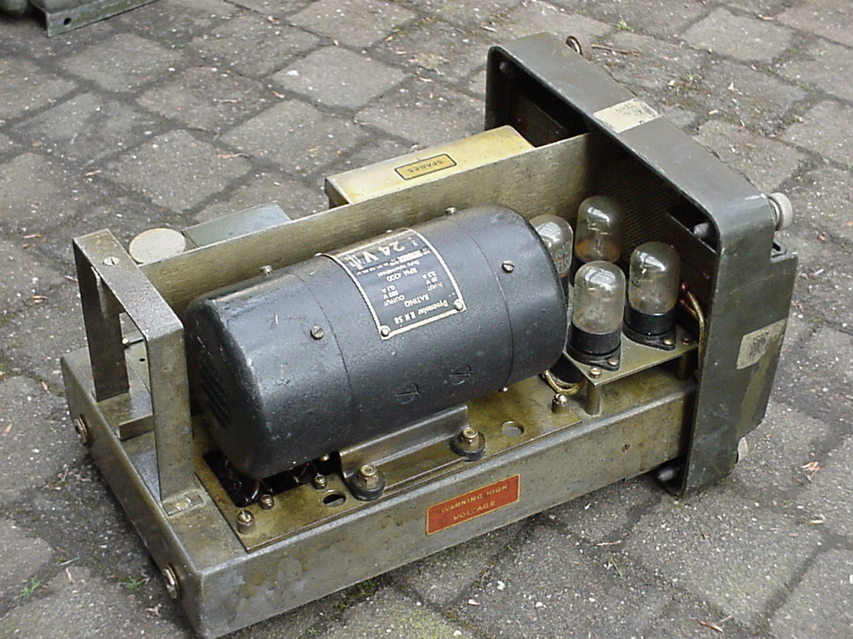
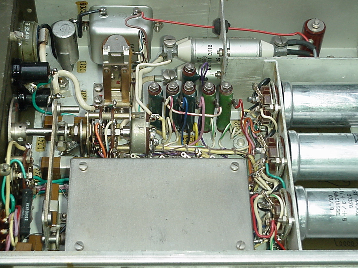
Although in mechanical design there is a big difference between the two PSU's from the point of view of electrical engineering the two
PSU's resemble each other very well. No technical schematics are available but it is easy to see that the basic design is equal to the
DY-88. A vibrator PSU for the 105 Volt for receiver and TX oscillator and a dynamotor PSU to give the high tension for the transmitter PA.
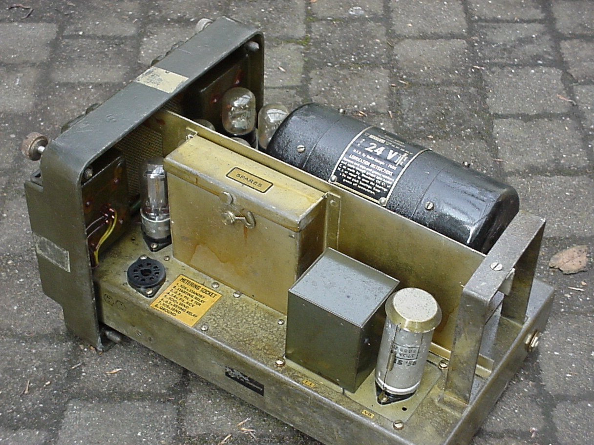
Also the spares box for field repairs equals the DY-88 design.
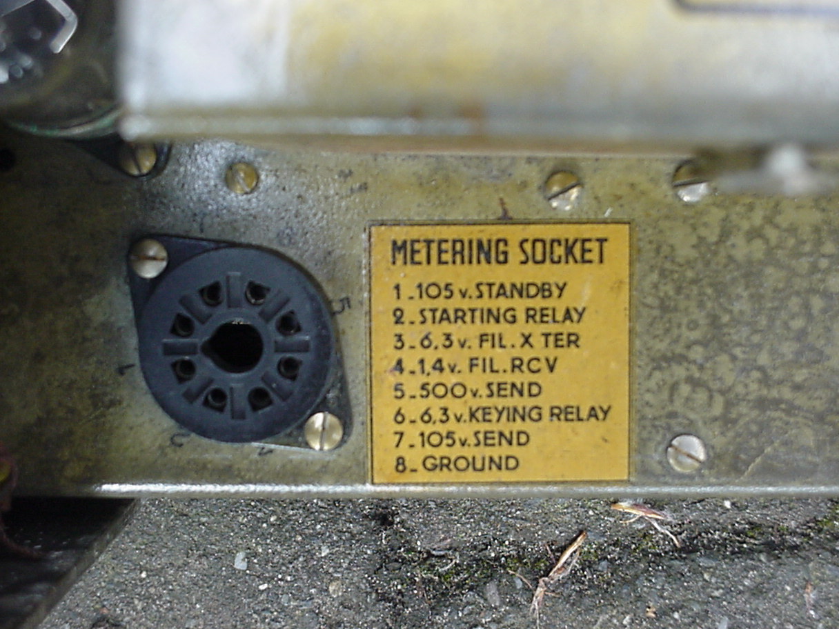
A good improvement in tejh ECDY-88 is the metering socket that allows quick voltage check-ups for repairs. If you have been involved in
field repairing the standard DY-88, youwil agree that such metering socket is what you really want. It can make repairs so much easier
and be completed in much shorter time.
It is a pity that Mr. Deibel lost the cover plate of the vibrator unit since this plate had a small tag with the schematic diagram showing
the low voltage circuit. If he finds it ever again, we will add a scan of it to this page.
If any of the readers have seen this rare PSU before, has a schematic diagram or manual or perhaps even have one… please let us know.
---- News Flash ----Dangerous ----Angry Nine ---- Radioactive ---- Warning ----
Most Angry Nine radios on the market now a days have regular white paint on the front panel to indicate 'what are all the knobs for'. However back
in the late 1970's and early in1980's most Angry Nine radios available on the surplus market in Holland were fitted with radioactive paint.
In fact there were so many radioactive Angry Nines - but to be honest also quite a bit of other military surplus radios like the AN/GRC-19 and the
VHF series radios based upon the RT-66, 67 or 68 series - on the surplus market that the Dutch authorities at one day decided to raid the most
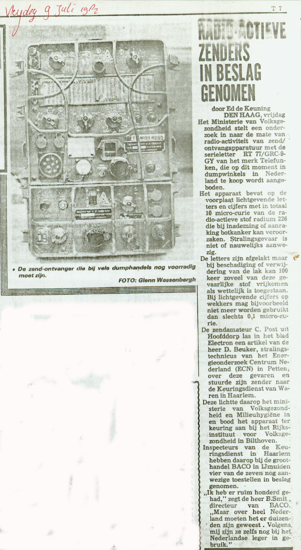
popular surplus store in the Netherlands: BACO at IJmuiden. This raid made the headlines (well headlines… it was on page 7) of the Dutch national
newspaper 'De Telegraaf' (The Telegraph) on Friday morning July 9-th, 1982.
These radioactive GRC-9 radios were released from Dutch Army war reserve warehouses and we up-graded by the Dutch military to meet the best
standards available for these radios at that time. The fact that the paint used is radio active is also indicated on the front of the radio
set. See the picture below.
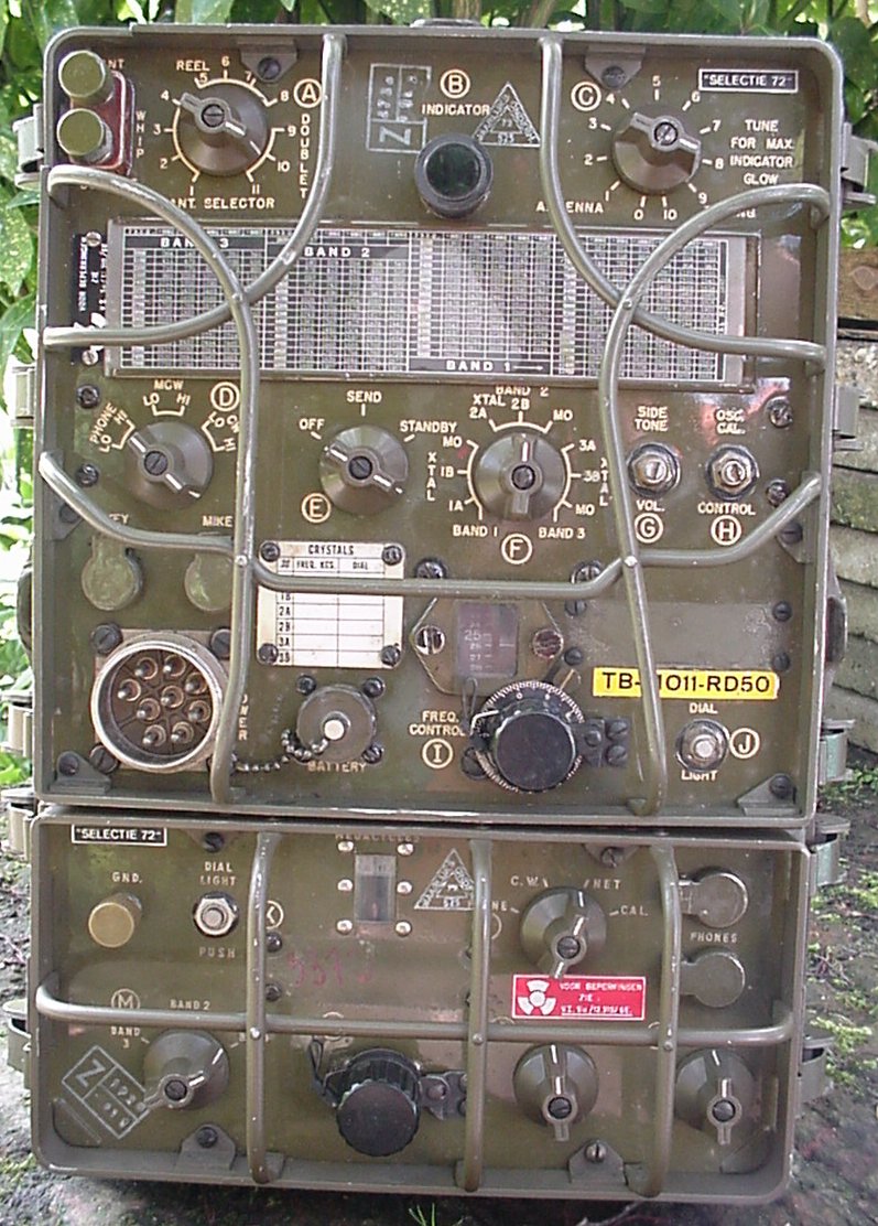
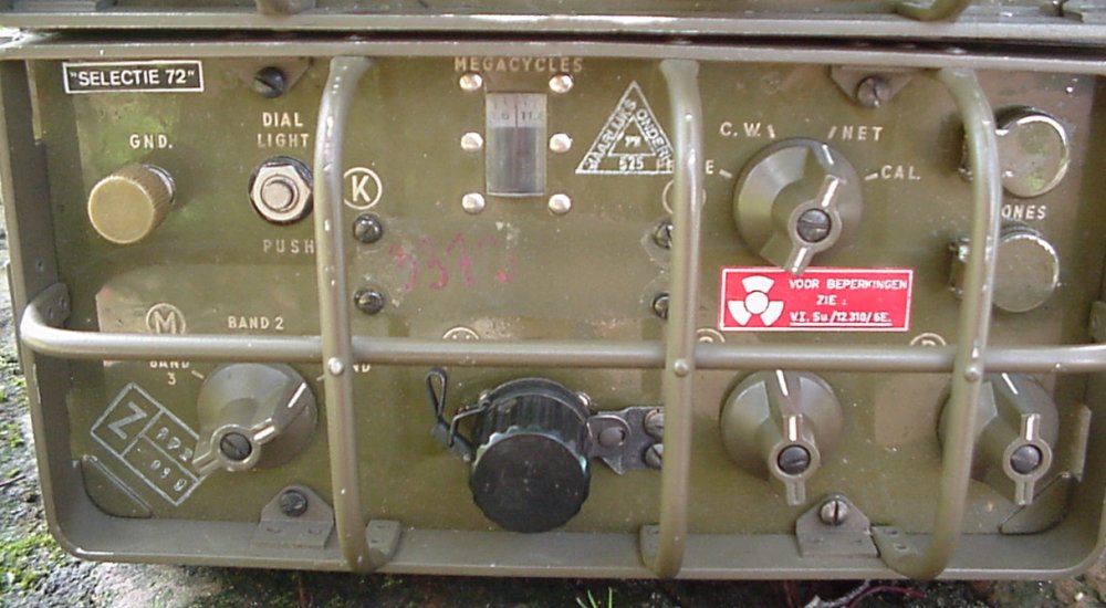
On the front of the receiver you can see a red ID tag with the International Warning Radioactive Source sign on it. It also mentions that
the radio set can be used according to the restrictions given in a special document. What this restrictions were… I have no idea. Were
they intended for the safety of the personnel operating the set or does it just indicate that the set can be traced - and thus fired
on - by the enemy using Geiger Counters?
A same ID-tag, but now in black, can be found on the front panel of the transmitter unit, next to the frequency chart. In fact most
often the radioactive warnings tags are in black on both receiver and transmitter unit. The red tags are not seen that often. Most
times these warning sign plates are made of aluminium but also plastic sticker versions have been noted (like in the above pictured
set the red sticker on the receiver unit).
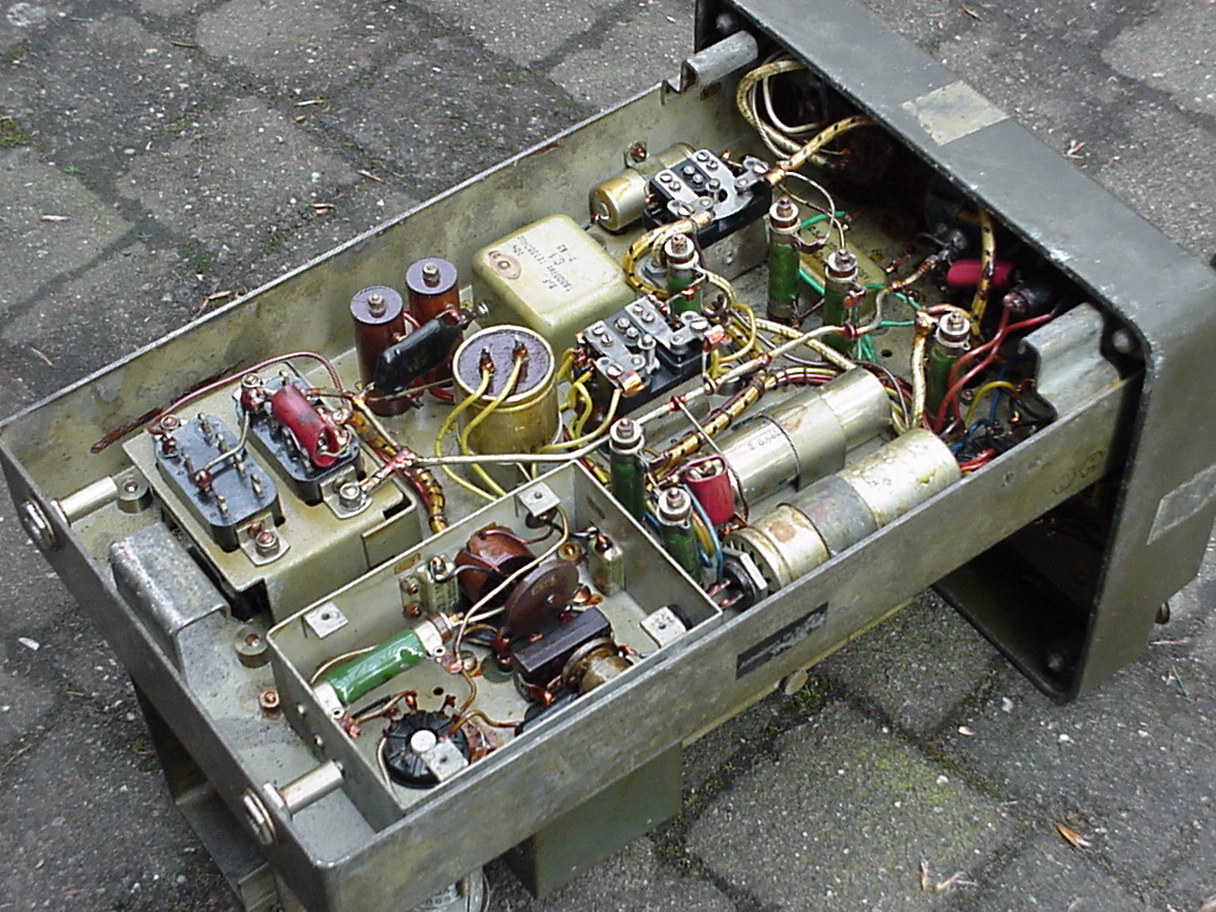
What does it all mean… well the paint used on these rigs incorporate radium elements that make the indications of the front 'glow in
the dark'. It is not the radiation for this paint that is the most dangerous, in fact all these radio active painted GRC-9's are
treated with a rather thick layer of lack that does attenuate the alpha rays radiation very well. No the danger is when the lack
cover is removed or broken and particles of the radio active paint can be touched by your hand. The likelihood is very high that
in this case these particles will also enter into your mouth or nose and that's were the danger is.
In practice only a hand full of these radio's were recovered from the surplus market by the Dutch authorities. It seem that they
were more successful in preventing any more radio active sets to come to the market since from that time on only GRC-9 with normal
white paint were available on the Dutch surplus market.
Of course the radio active issues became the 'talk of the town' for Dutch military surplus radio lovers and the radio active
Angry Nine became some sort of pariah. Since it is not always easy the see the difference between radio active paint and old normal
paint, especially if you have not the expertise to discriminate between them, and also given the fact that some GRC-9 with regular
paint but with the radio active warning sign on it appeared on the Dutch market it became a habit to remove the Radioactive Warming
Sign plate form the sets. With this sign on it the set would not sell. Without the sign it did sell great! So the conclusion is simple.
Many removed the Radioactive Warning Sign plate from the set since it is only hold by two small screws. However, simple CSI techniques
will unmask the crooks. Two little holes on the receiver front and on the transmitter front next tot the frequency chart.
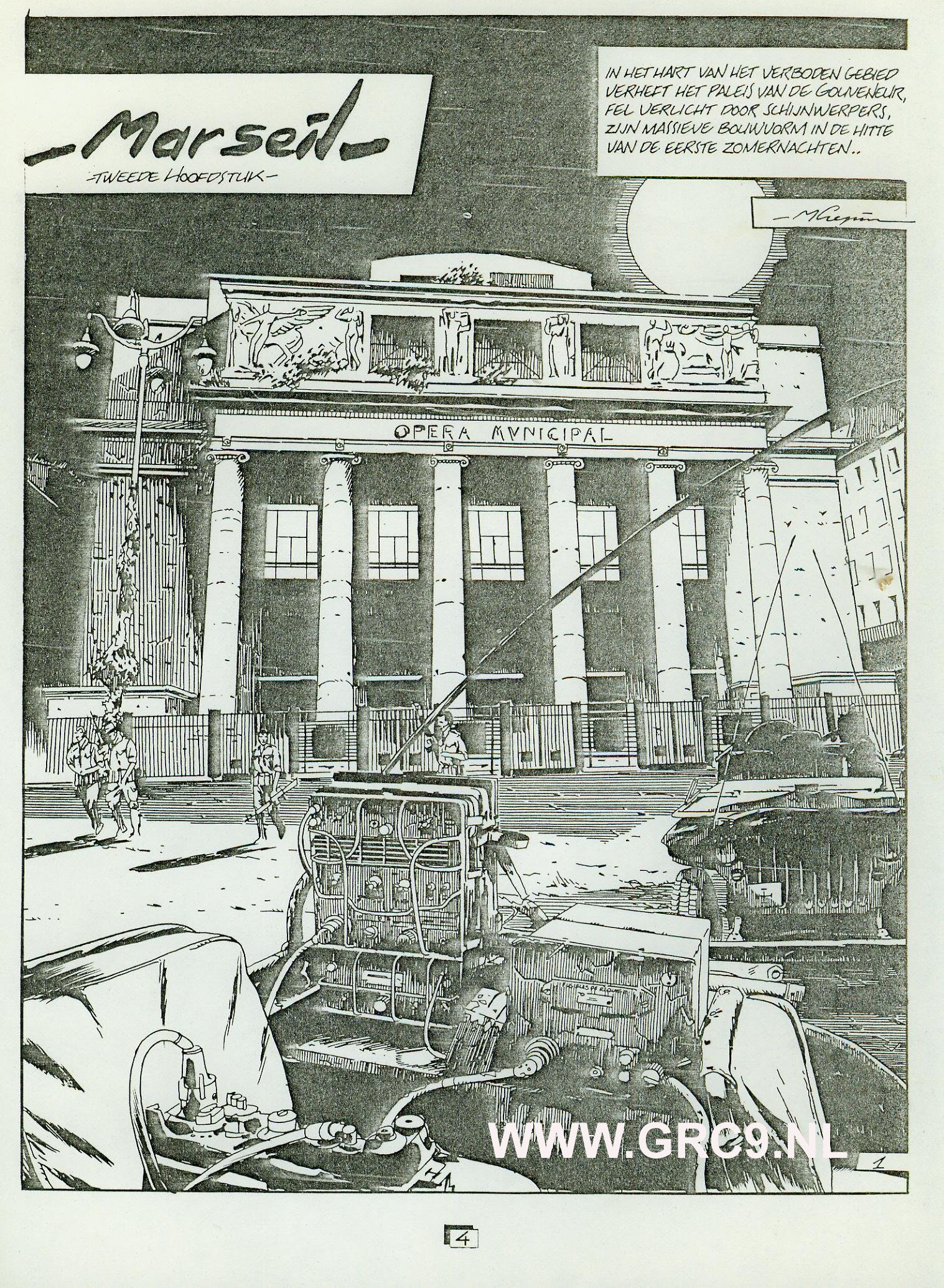
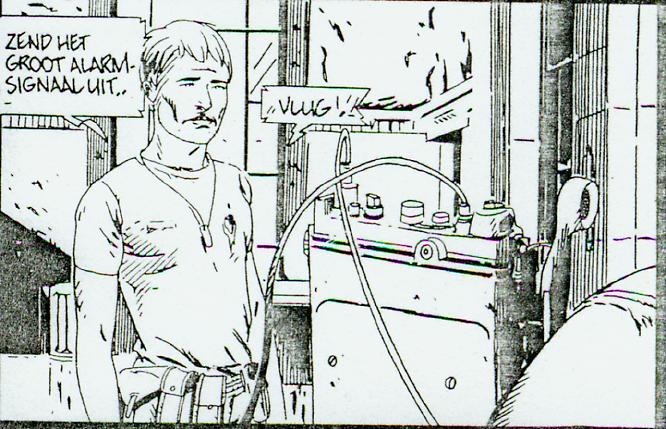
Comic book hero.
The author of this comic book must have been a true lover of the Angry Nine.
Look at page 4 to the opening scene of chapter two of a story called 'Marseille'. A military jeep with an AN/GRC-9 drawn to real live. Both the radio set and the installation of it in the vehicle are very realistic. Look for yourself and see how the radio set, the DY-88 power supply unit, the LS-7 loudspeaker and even the connectors at the interconnection cable CD-1086 are all drawn exact - in minor details - to the original.
Also look at the FM radio. Of course one can not tell from the drawing if is an AN/PRC-8, or 9 or 10 but again, it is an exact copy of the original.
On page 13 the PRC radio is seen again.
Known by many names.
'Angry-Nine' is the most well know nickname of radio set RT-77/GRC-9.
This radio is the main part of US origin radio-installation AN/GRC-9. For the French and German 'offshore' build versions the nomenclature is AN/GRC-9-Fr and AN/GRC-9-Gy. So far nothing new. However it is not generally known that the same radio set RT-77/GRC-9 is also the main part of radio-installation AN/GRC-87 (12), AN/GRC-87 (24) and AN/VRC-34.
These radio-installations are basically standard GRC-9 installattions but the accessories that go with the radio are modernized. E.g. instead of the wartime headset HS-30, the newer type H-16/U is used. The loudspeaker LS-7 is replaced by a new model LS203U. Microphone T-17 is replaced by microphone M52U and hand generator GN-58 is replaced by model GN43/6.
Major differences to the old GRC-9 installation outfit are power supply unit DY-105 (dynamotor unit 24 Volt only) and field strength meter ME-61/GRC that are introduced with the new outfit.
To get a full understanding of the compete new outfits see the TM's below. Note that some of these TM's are dated as new as November 1977. In most NATO countries the GRC-9 radio was already obsolete for at least 5 - 8 years in 1977. Perhaps these outfits are intended for non tactical purposes of reserve army use?
TM 11-5820-453-10.
TM 11-5820-453-20P.
TM 11-5820-453-34P.
A rare DY-88 Fr.
Only once over all the years I’ve seen a DY-88 Fr supply unit that had an extra switch for use with the GRC-9 or SCR-694 (BC-1306). Of course I bought it and add it to my collection of ‘rare GRC-9 items’. It seems that this switch is added already during the initial manufacturing of the unit.
Let’s have a look:
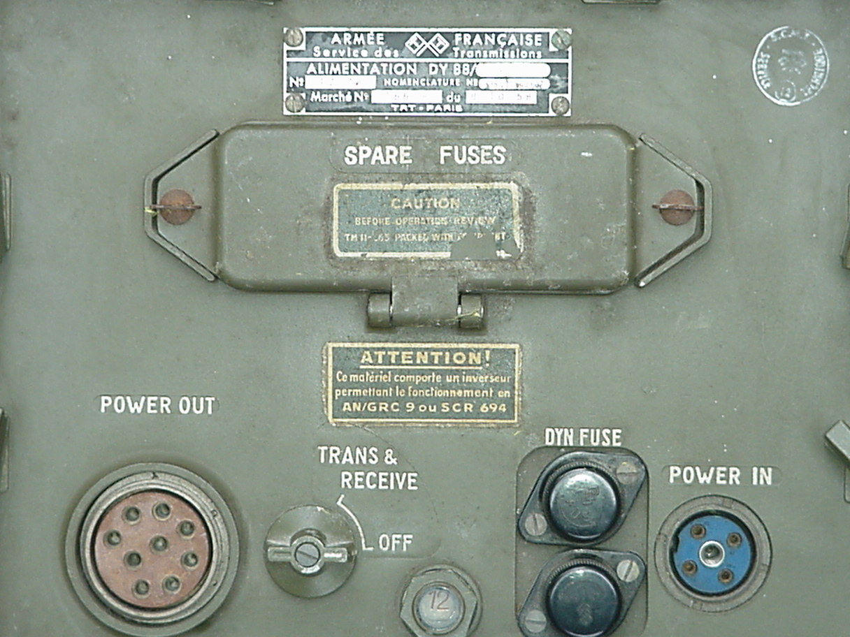
It’s quite clear.
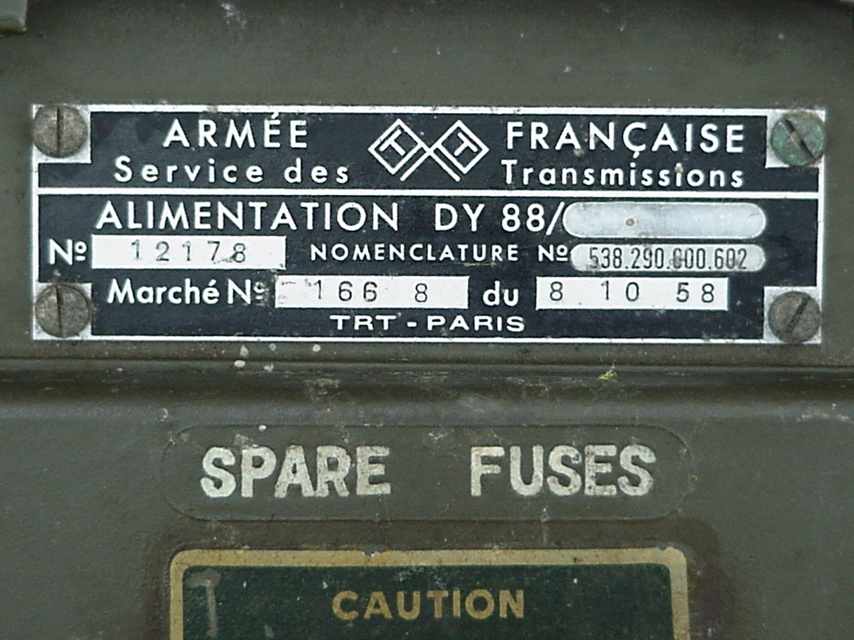
The internal switch is mentioned ( ATTENTION! ) on the front of the
unit. The French production (year 1958) is also clear from the ID-tag (see
below for close-up) and the actual use of this DY-88 within the French military
is clear from the round stamp on the right top corner of the front.
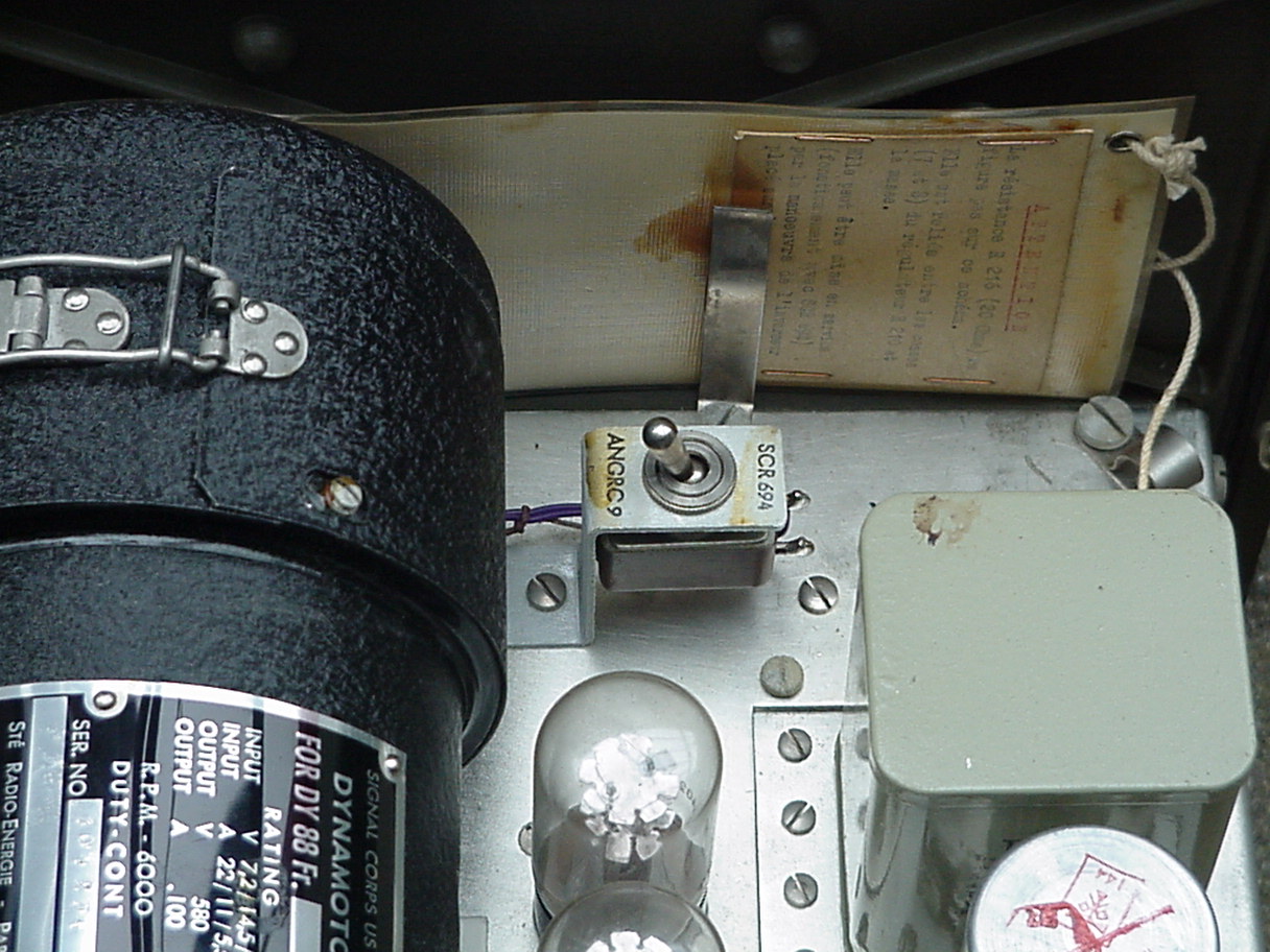
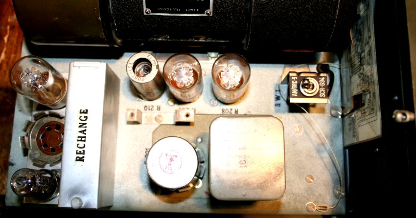
How does it look at the inside?
Well as you can see the switch is mounted on the top of the chassis, behind the front plate and next to the dynamotor.
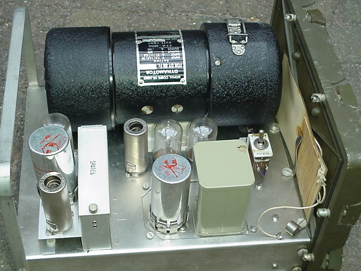
As you can see inside it is just a regular French production DY-88 with the only difference the added switch.
See detail picture below.
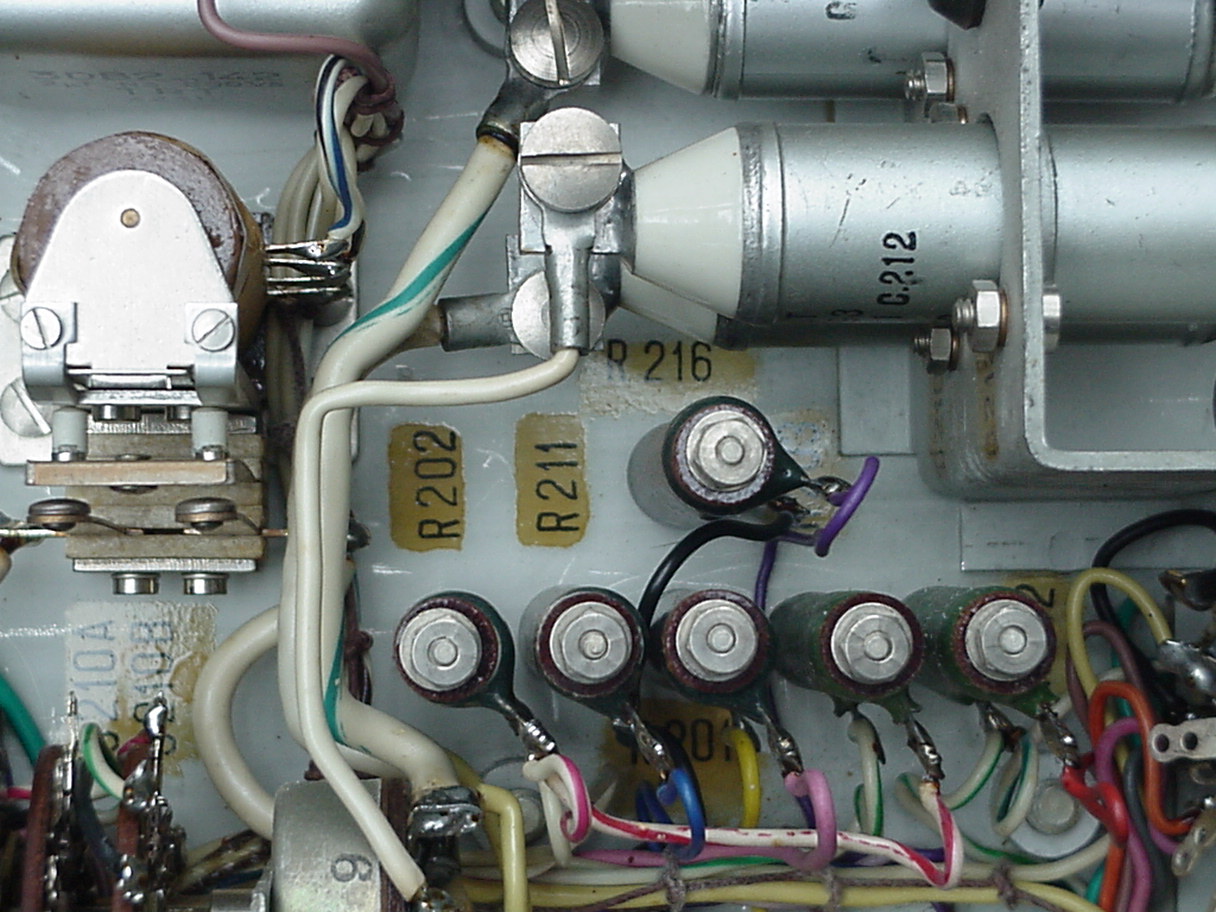
What is the modification exact?
Well that is very simple. It is just one resistor (R-216)of 20 Ohms. One side of the resistor is connected to ground (black wire) the
other side is connected via the switch to pin 7-8 of the ballast tube R-210 (purple wire). In the position AN/GRC9 the switch is open.
In the position SCR694 the switch is closed bringing R-16 over the R-210 ballast tube and thus gives an extra current load.
This is logical since the BC-1306 has a lower filament current drain then the AN/GRC-9.
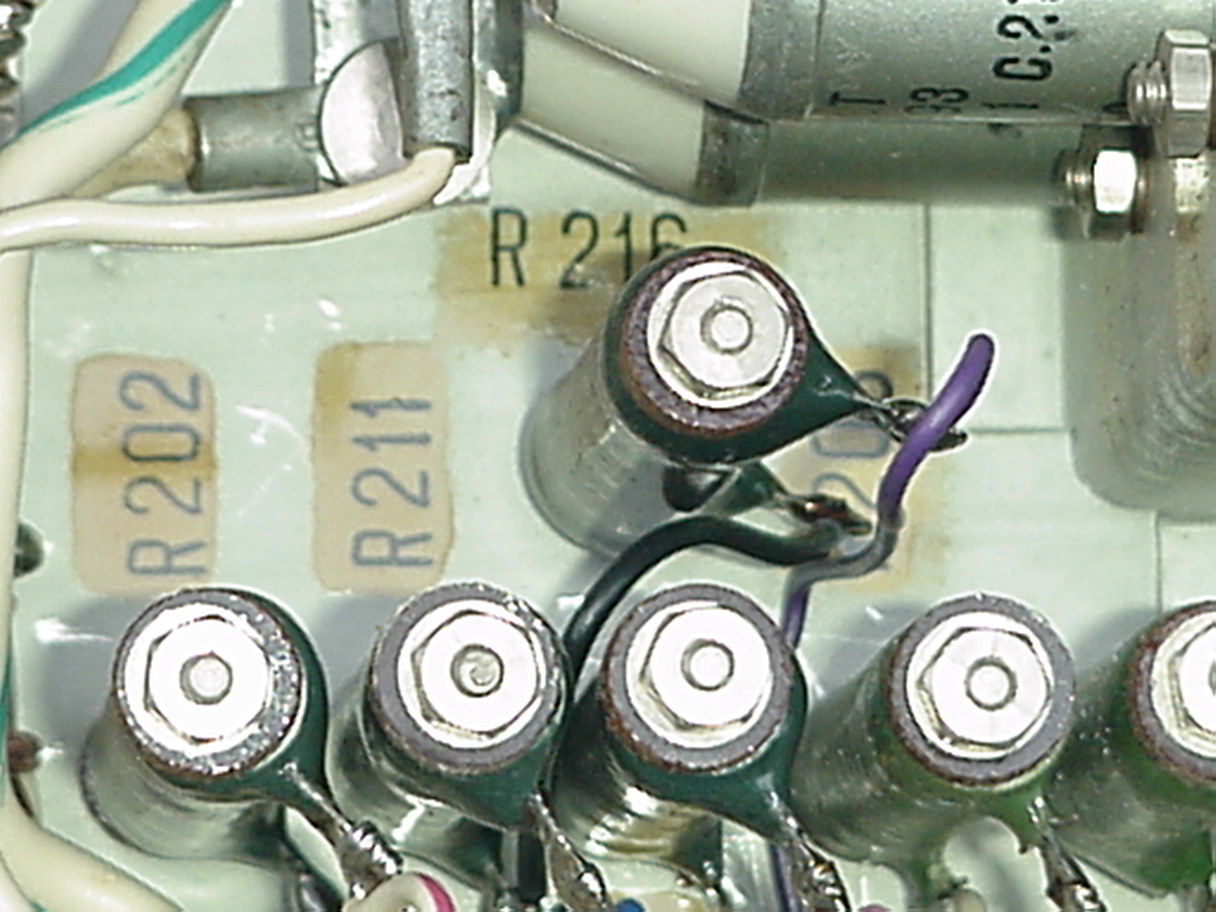
A few more detail pictures of this rare unit showing the position of R-216.
Has anyone seen this unit before?
In answer of the question from Wim I looked into mine collection.
And found this DY-88/SCR-364/GRC-9-FR
It’s quite clear.
The internal switch is not mentioned on the front of the unit, there is a clear description on the ID-tag. The French production (year 1963) is from
later date (see below for close-up) and the actual use of this DY-88 with in the French military
is also clear from the stamp on the right top corner of the front.
How does it look at the inside?
Well as you can see the switch is also mounted on the top of the chassis, behind the front plate and next to the dynamotor.
As you can see inside this unit is also a regular French production DY-88 with the only difference they added a switch.
What is the modification in this unit?
Well that is very simple, there is no difference with the unit mentioned in the articel of Wim.
Has anyone seen this type of unit before?
Telefunken en de GRC-9
Na de Tweede Wereldoorlog was het Duitse bedrijven strikt verboden om activiteiten te ontplooien die in verband stonden met research, ontwikkeling of productie van radiocommunicatieapparatuur. Al na een paar jaar werd dit verbod al weer versoepeld en later zelfs helemaal opgeheven maar het gevolg van dit verbod was wel dat de Duitse industrie de aansluiting met de stand der techniek kwijt was.
Er was hierdoor een behoorlijke technologische achterstand opgelopen op het gebied van moderne telecommunicatieapparatuur. De enige oplossing om deze achterstand weer in te kunnen lopen was door aannemen van 'nabouw' opdrachten van de Amerikaanse overheid om zo ervaring op te kunnen doen met de productie van apparatuur die voldoet aan de meest moderne eisen.
De Telefunken fabriek in Berlijn was in 1953 de eerste Duitse firma die een dergelijk 'nabouw' verzoek op basis van een z.g. 'Off-Shore' overeenkomst van de Amerikaanse overheid ontving. Het betrof de nabouw van de AN/GRC-9 kortegolf zend-ontvanger die, hoewel gebaseerd op een al wat verouderde technologie, operationeel nog veel werd gebruikt en waarvoor dus extra productiecapaciteit nodig was.
Voor de firma Telefunken was deze opdracht een regelrechte uitdaging. De productie moest overeenkomstig de strenge Amerikaanse eisen en normen (de MIL-standaarden) plaatsvinden, iets waarmee in Duitsland destijds nog geen ervaring was opgedaan en waarvan niemand bij Telefunken dan ook op voorhand kon voorspellen of men deze opdracht dan ook tot een goed einde zou kunnen brengen.
Na intensieve onderhandelingen werd door Telefunken in februari 1954 een overeenkomst gesloten voor de levering van een eerste serie van 6000 stuks GRC-9 installaties. Eind 1955 volgde een tweede opdracht voor de levering van nog eens 2500 stuks. Voor Telefunken waren deze twee Amerikaanse opdrachten, met een omvang van maar liefst 50 miljoen DM, een geschenk uit de hemel. Het gaf de firma een stevige zet in de juiste richting om zo weer mee te gaan in de vaart der volkeren.
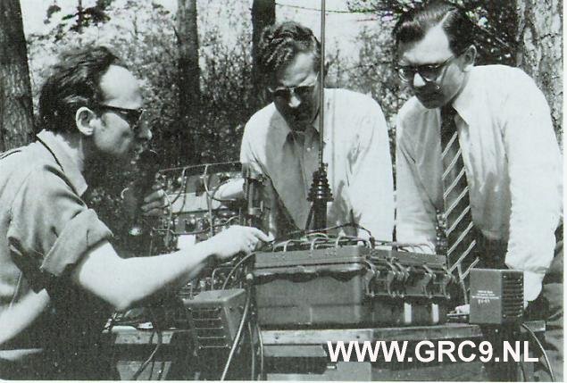
Veldtesten met de GRC-9 door Telefunken personeel in de bossen bij Berlijn.
Na de nodige opstartproblemen, waarbij Telefunken zich eerst moderne productietechnieken eigen moest maken, verliep de uitlevering
van de overeengekomen aantallen GRC-9's, eerst vanuit de fabriek in Berlijn en later vanuit de Telefunctie locatie in Ulm, verder
zonder problemen. De ervaringen met het nabouwen, het kunne voldoen aan de MIL-standaarden en de productie van de GRC-9 zijn door
Horst Schutzendubel in 1956 beschreven in een artikel in een vakblad.(zie bronnen.
Bronnen:
'Vom Knalfunken zum Datenfunk; 75 Jahre "Bewegliche Stationen", ein Beitrag zur Geschiechte der telefunken-Klein-funkgerate', Alfred Engelmann,
Uitg. AEG Telefunken, Ulm, zj (rond 1977).
'Erfahrungen bei der Reproduktion von Nachrichtengeraten der USA', Horst Schutzendubel, ETZ-B, Bd.8, H.10, 21.10.1956, pp 367 - 371.
GRC-9 artikel uit RAM 128, februari 1992 geschreven door Wim Kramer.
Afstemmen van de antennes op de GRC-9, geschreven door Wim Kramer.
De R-77, geschreven door Wim Kramer.